DEFCON 25 HHV Challenge - Part 1: Initial Investigation

Disclaimer: My (not so) Illustrious career in Hardware RE
Many people don’t know this about me, but I can do hardware reverse engineering, although I hide this fact. The reason is that I can do it but I’m shitty at it.
Traditionally, I’m a software reverse engineer (hell, I have a Computer Science Degree). I’ve looked at everything from desktop application software to embedded firmware. I’ve worked on many common architectures such as ARM, MIPS, x86 / x64, and some esoteric architectures, and over the years, I’ve worked my way “down the stack” closer and closer to hardware.
Hardware RE is not my strong suit, but I enjoy it when I get the chance, and I’ve picked up a few great tricks from some great hardware hackers.
Inspiration
So, a confluence of events led me to this project. While cleaning up my basement, a Ben Eater video found its way into my feed. He was breaking down an old TV censoring device, dumping the flash and revealing the word lists it used. I highly recommend the video, it’s a banger.
If I’m honest, I had never heard of Mr. Eater and was inspired to find some hardware hacking myself.
As a side note, I asked many of my friends and colleagues if they knew who Ben Eater was and I discovered that everyone knows who he is. I’m just out of touch.
In the meantime, I ran across a PCB I had bought in the Hardware Hacking Village of DEFCON 25. I remember being told that it was a easy-to-medium hardware RE challenge, so instead of organizing my basement, I got nerd sniped into looking at this PCB. I don’t remember there being any instructions on it, but as I’ll show later, there actually were some which would have been helpful.
The Board
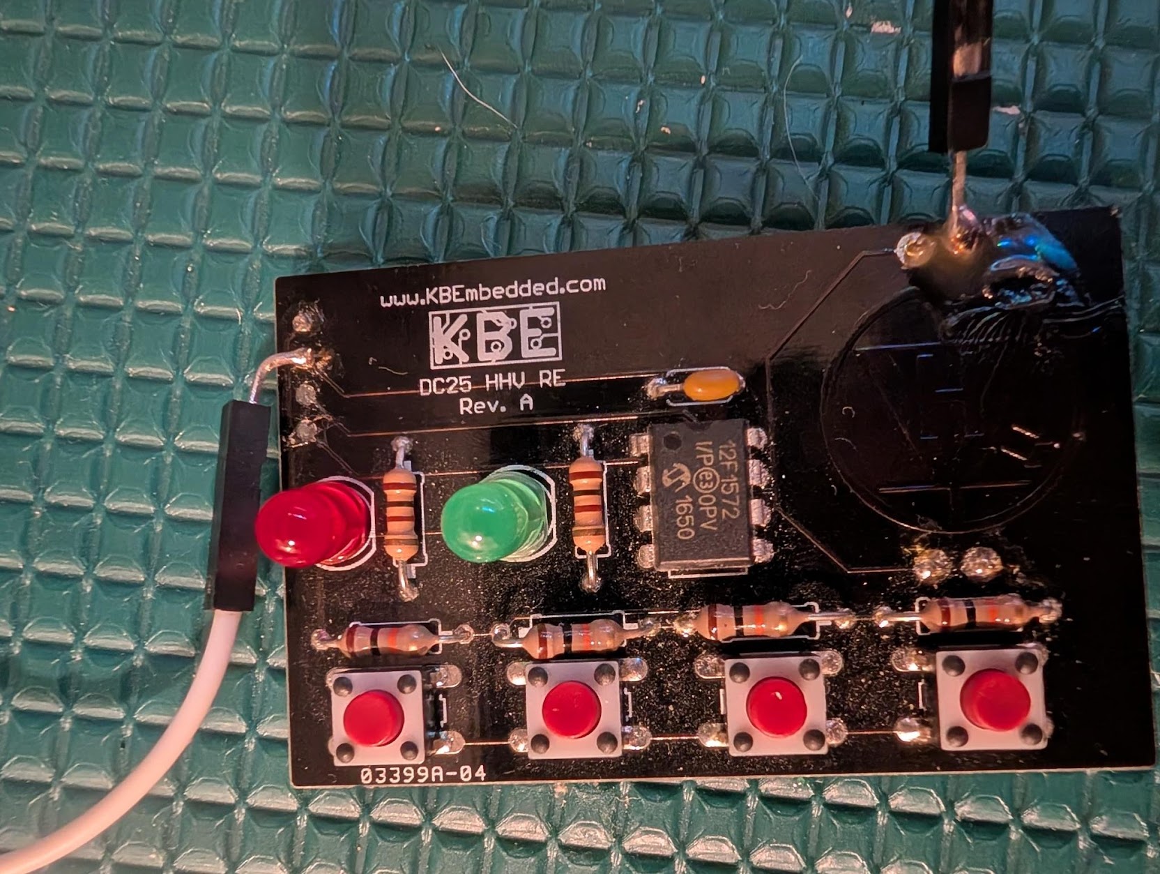
To interact with the board, you put a coin cell battery in the back, and you’re greeted with a green LED flashing on and off six times. Pressing a button flashes the red LED
and after pushing eight random buttons, the green LED flashes rapidly for several seconds before you can start pushing buttons again.
After finishing this challenge and the write up, I was digging through the original documentation and noticed that my red and green LEDs are in the wrong location. This was probably my fault when I soldered the board together.
After burning through four or five coin cell batteries, I soldered the DuPont connectors to the board because this it drains the coin cell batteries within a few hours. This decision also had the benefit of making the board easier to reboot.
The Chip
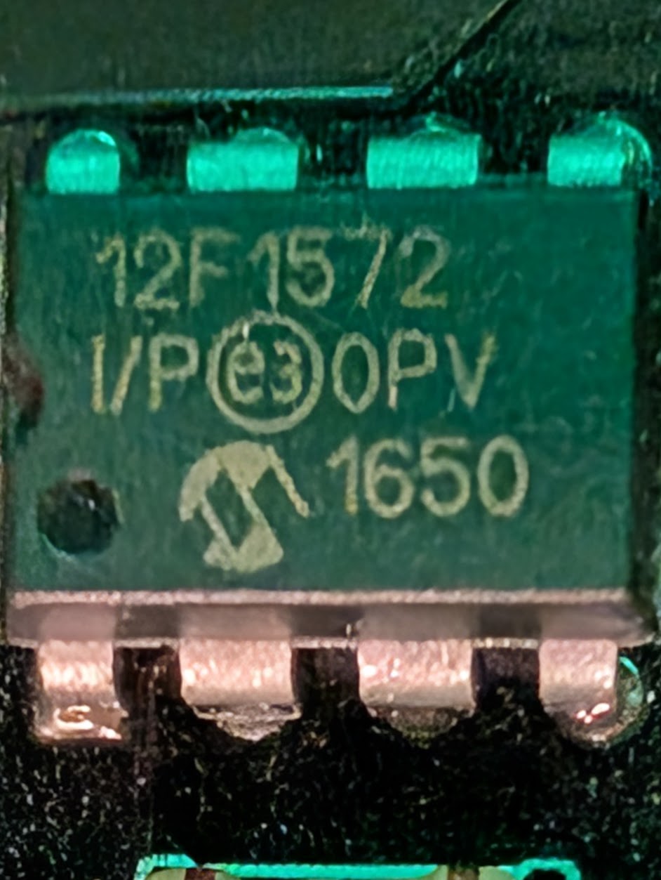
The board itself is pretty simple with only one real IC, right in the middle of the board - a Micron PIC12F1572. After a quick Google search, I was able to pull up the
datasheet, here. It looks like a little microcontroller with an operating voltage of 2.3 - 5.5v.
My main interest, at this point, was to get an idea of the chip’s pin out so I can start to identify functionality.
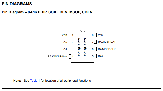
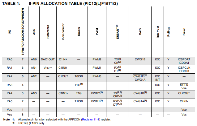
With the exceptions of VSS (ground) and VDD (power), the other pins can almost be configured to act as several different things.
Using my multimeter, I was able to beep out the pins of the chip easily. You can see my bad circuit diagram below. No promises of accuracy, this was just a super rough schematic so I could keep track of everything.

The four buttons are tied to a voltage ladder connected to RA2. This method of connecting the buttons allows the designer to determine what button is pressed by how much voltage is read in an ADC, while only using one pin on the chip. This indicated to me that RA2 was going to be an analog to digital converter (ADC) pin, and if you look at the pin out, above, you’ll see that R2 is in fact able to be ADC2.
In addition, you can see that RA4 was tied to the green LED and RA5 would be tied to the RED LED.
Beyond Vss and Vdd, there were only three mystery pins. RA3, RA0, and RA1. Looking at the datasheet R3 can be used for reset, as well as a programming voltage (which we will get to later). Which left just RA0 and RA1.
The first thing that I decided to look for was if any of the pins were transmitting information via UART. This is common in both hardware challenges and real-life electronics.
If you’re unfamiliar with UART, it stands for “Universal Asynchronous Receiver/Transmitter”. In data sheets you may see different versions such as USART (Universal Synchronous / Asynchronous Receiver / Transmitter), or EUSART (Enhanced USART like in our datasheet. But everyone just calls it “UART”.
UART can be used for a lot of things, but it’s most often used for sending and receiving textual, human-readable information. In some cases, such as the TpLink Archer D7 wireless router, the UART interface provides an entire console that you can interact with.
However, I really didn’t have a ton of equipment at home to test that theory. Most of it had been lost in a move across the country or at a job where I brought it into work and forgot it there.
So, I ordered a cheap power supply and a couple FTDI232 USB breakout boards (that support 3.3v).
Phoning a Friend
One very useful big-ticket item I’ve never owned is an oscilloscope. So, I started looking at buying one online. I quickly got lost trying to figure out which one would be the best for me, considering my light usage. That’s when I reached out to my friend and former colleague Matt Alt of VoidStar Security for advice on what to buy.
If you don’t know Matt, he’s the real deal. Where I just pretend to know what I’m doing, he’s easily the best hardware hacker I’ve ever had the pleasure of working with (and I’ve worked with a fair number).
Over a couple of beers and after asking about different brands, Matt offered to let me borrow his spare Siglent oscilloscope. I took him up on the offer, and the next day, he presented me with not just a scope but an entire care package including clips, connectors, an LA1010 logic analyzer, and a DSLogic Plus, way more than I could have ever expected.
Getting back home, I quickly set up the oscilloscope and started probing pins RA0 and RA1. Nothing of note was coming out of RA1, but when I probed RA0, this happened:
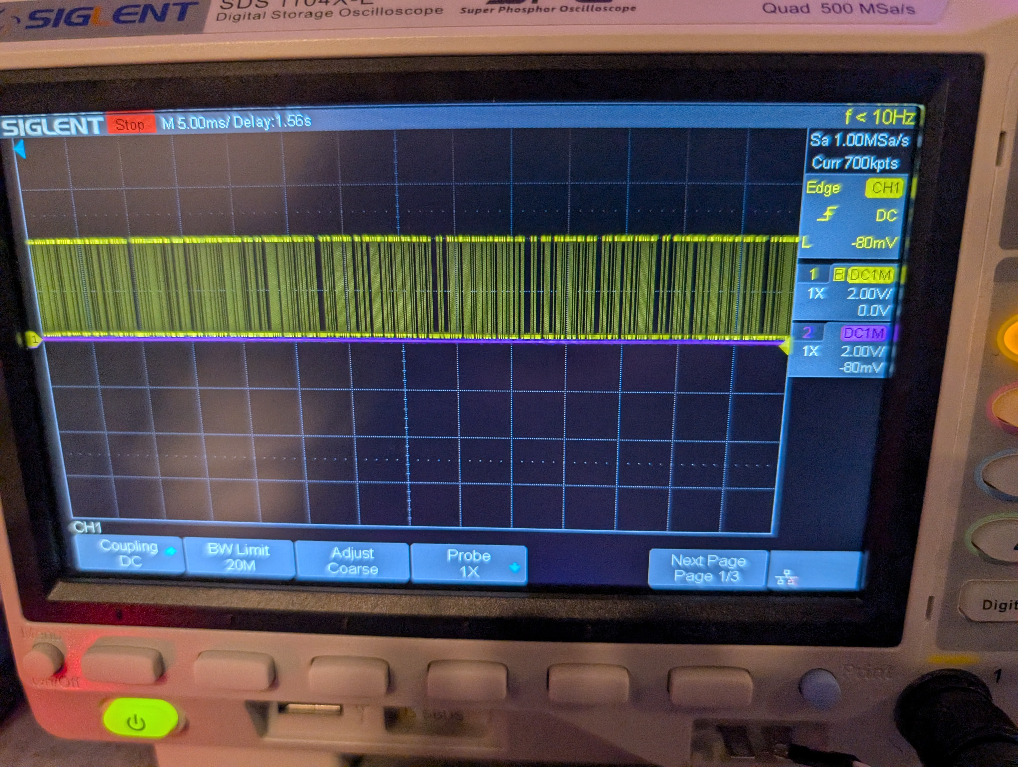
This is a distinctive pattern for UART. You can’t see it in the image above, but the data came out in bursts and only after a power cycle. This can be a strong indicator that you’re looking at UART. It could have been some other digital communication standard, but since this pin can be set to be UART TX, it’s very likely that what we’re seeing is textual data transmitted via UART.
You might be asking why I chose to use an oscilloscope instead of setting up a logic analyzer. Both would have been perfectly acceptable solutions, but when I’m just investigating a board, I like probing around with an oscilloscope first since I can move around probing things more quickly. I can then set up the logic analyzer once I’ve decided something is interesting and dig deeper.
I ended up setting up a raspberry pi 3b to my FTDI breakout board. I guessed the baud rate to be 9600 and was both excited and slightly annoyed to see partial strings coming out.
As a quick tip, it’s almost always 9600 or 115200 baud. Start there.
Why were they partial strings? This issue could be many things: a line length problem or a grounding issue. This was a little annoying, but after jiggling the wires and putting a logic analyzer in the middle, I got the following message in the logic analyzer.
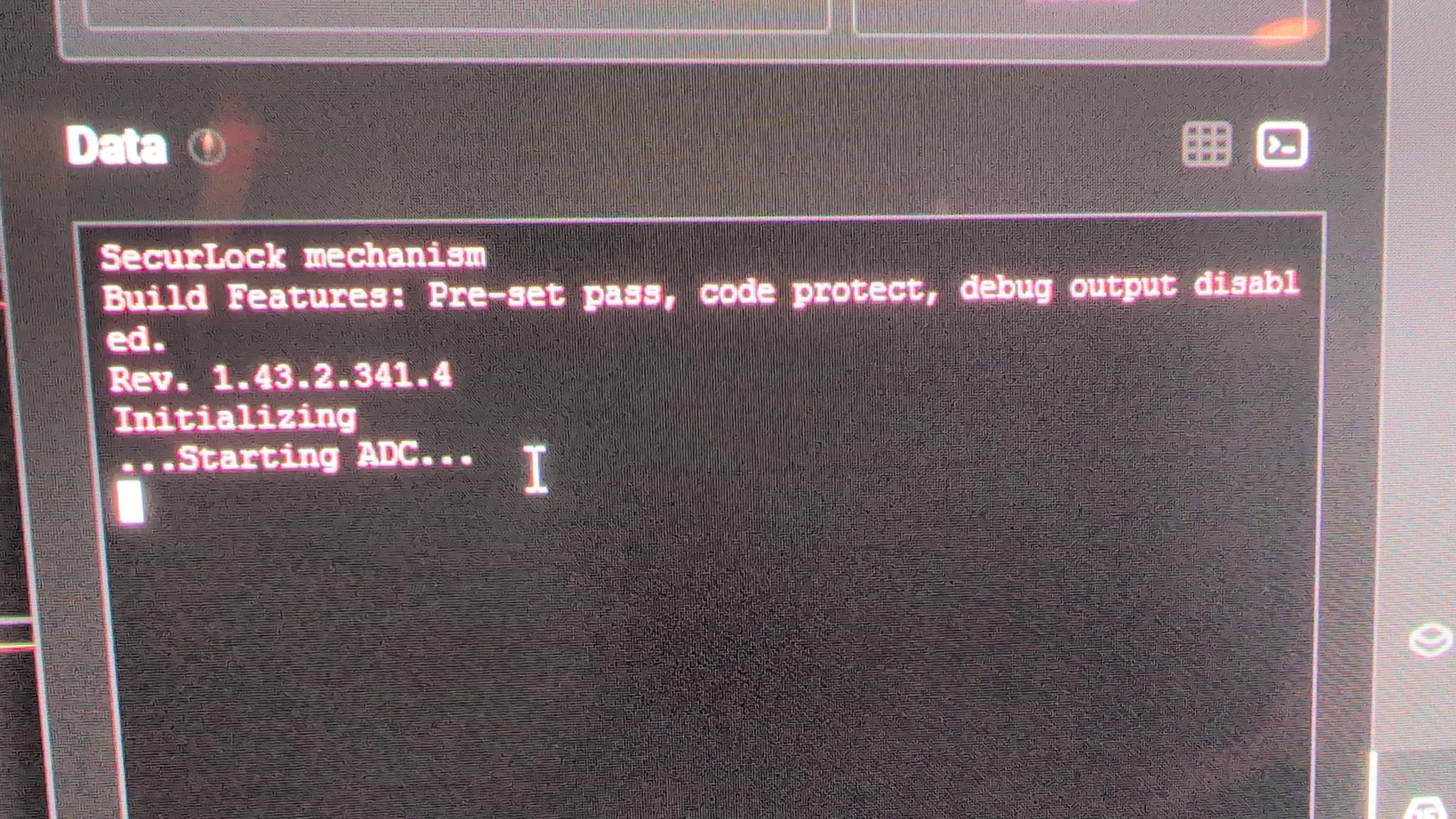
Don’t tell me you do anything more sophisticated than jiggle or reseat the wires. I know you don’t. You jiggle those suckers until your data looks better and you know it.
Now we’re getting somewhere. I’d hoped to get more output from UART when I pressed buttons, I typed a random eight button sequence, but nothing more came out.
This left a single mystery pin RA2. Since it can be set to be the UART receive pin, I decided to hook it up to the FTDI242 board and try typing something.
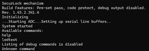
In this case, the UART bytes that are typed by me on the keyboard are not actually echo’d back out, but when you press “enter” the device responds. In this case, there are (seemingly) only two commands available, ledtest and help.
Typing help gave less than helpful help, with only two commands, and typing ledtest just blinked the LEDs a bunch of times. Nothing substantial.
I tried several things at this point, attempting to try to guess commands, all with no avail. I even tried to type in a bunch of data to see if the challenge had something to do with a buffer overflow. That also didn’t work.
We were going to have to dig deeper.
To Be Continued …